Hardware vulnerabilities in smart locks
Table of Contents
We evaluate the hardware security level of the smart locks, disassembling one and analyzing the elements that make it up
We got our hands on a Yale Linus smart lock, one that you can operate from your smartphone, so we thought it was an excellent opportunity to practice many of the hardware hacking concepts and IoT security testing methodologies we have seen here in the past. Over the following few articles, we will walk through the security assessment process of smart locks and tell you our conclusions.
Obtaining information for hardware analysis of smart locks
The existence of design flaws in the hardware can make a smart lock no longer secure. This security breach would allow us to interact with the device without authorization. Therefore, a thorough review of the hardware is a critical task.
If you are familiar with OWASP FSTM, you will know that the first step in this methodology is to look for manufacturer’s references, designs, or code leaks in search of the device’s firmware.
Unfortunately, the initial search in open sources, the manufacturer’s website, and code repositories such as GitLab, GitHub, git, etc., has yielded no results. We have also searched in forums of electronics developers and the Dialog / Renesas forum of the DA14680 microcontroller manufacturer used in this device. It has yet to be possible to locate relevant information on this lock.
Aspects to review during hardware analysis
After having exhausted the identification and downloading of the firmware online, we proceeded to the next step recommended by OWASP FSTM. This step consists of searching the board for a port (JTAG / SWD debug, UART interfaces, SPI to Flash memories) that allows us to extract the firmware from the physical device.
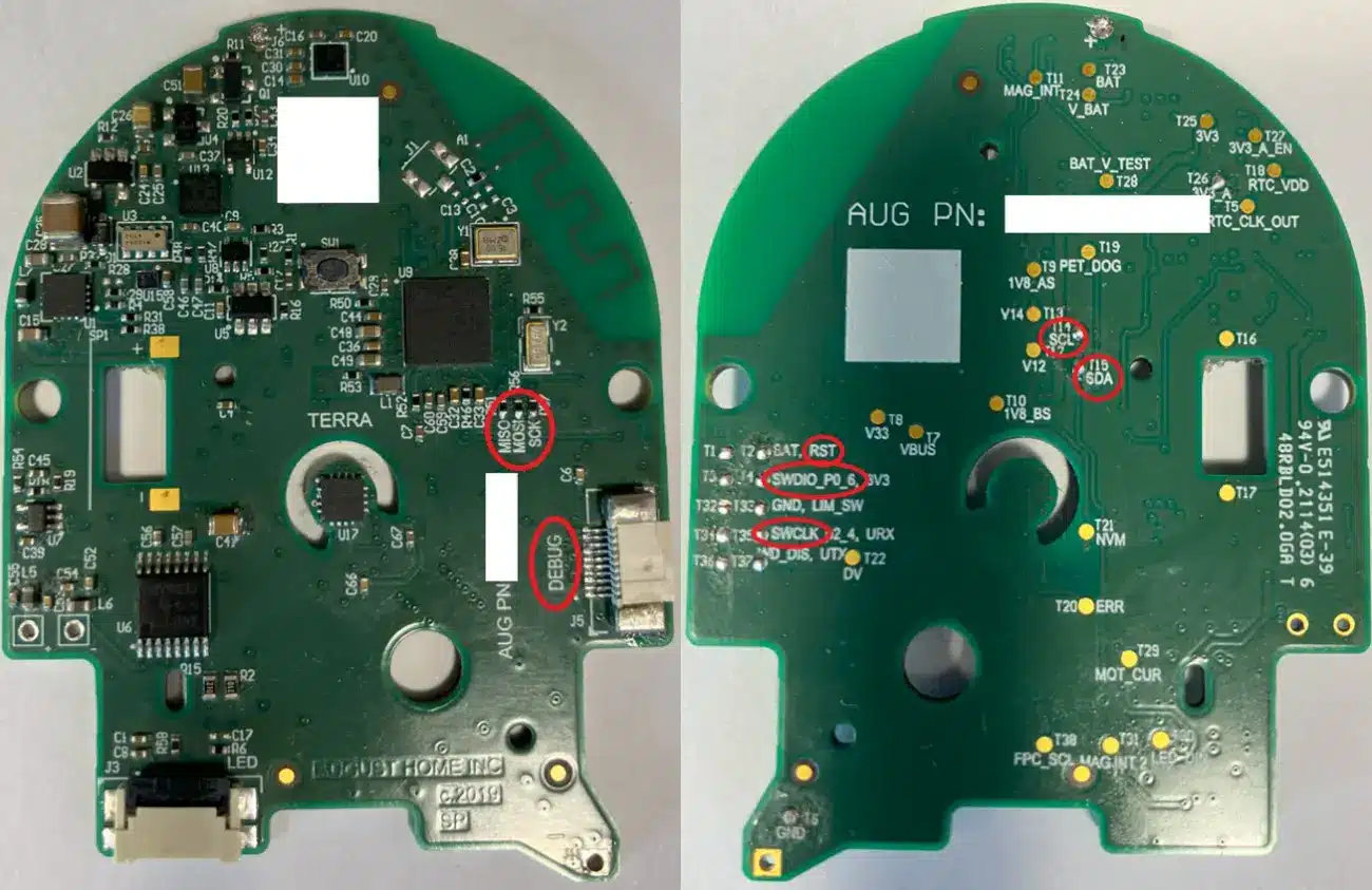
The device is completely disassembled to locate these ports, and its components are checked. It is advisable to locate the operating regions of the smart lock board to narrow down where ports may be present that are not identifiable to the naked eye.
The PCB analysis should locate both exposed ports and test points that may be part of a debug interface to communicate with the microcontroller. A debug port should not be present in a production hardware design because, when enabled, it allows to take control of the firmware execution thread.
The microcontroller in charge of controlling the operation of the smart lock belongs to the manufacturer Dialog / Renesas. Specifically, it is the DA14680A model. It is identified that it uses the Cortex M4 architecture and manages various components located on the board, such as an accelerometer/gyroscope, a magnetometer, a lighting controller, a real-time clock, and the current amplifier.
Further review of the component datasheet can help identify the type of communications bus used.
There are multiple types of debug ports for the microcontroller under analysis because it has SWD, UART, I2C, and SPI debug capabilities. It should be noted that the UART, SPI, and I2C communication protocols, in addition to providing debug capabilities, can be used as communication ports between the sensors and the microcontroller.
Open UART interfaces allow the user to learn about the boot process or debugging of the audited system. Although they are not as potentially harmful as a debug port, sometimes, this interface provides information that can be vital to vulnerability. Therefore, it is not recommended to make it available. For example, on microlinux systems, a firmware dump can be performed from the serial interface.
Flash memories are rarely found on I2C interfaces, so they should be examined for them. It is very common for these interfaces to handle sensitive information, such as the exchange of authentication credentials. Extra information about the devices that communicate through this bus can also be found in them.
SPI interfaces mainly perform high-speed data transmissions and commonly exchange information with devices such as RAM or Flash memories. It is common for Flash memory data to be transmitted encrypted, so it is better to use a debug port (UART debug) to read them.
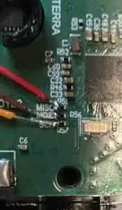
As mentioned at the beginning, in many cases, there is no port as such on the board to capture the information. It is necessary to use test points, soldering wires, or putting test clips on the legs of the components to identify if it is a communications bus and to be able to read it.
Communication ports located on the smart lock
On the board of the device under study, practically all the ports that have been mentioned have been located.
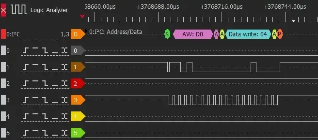
I2C port
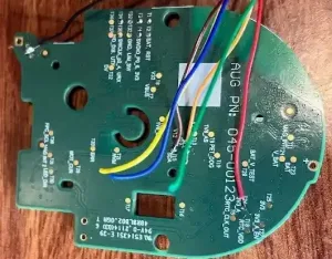 The I2C BUS communications have been analyzed, and communication frames corresponding to 4 devices (magnetometer, accelerometer, LED controller, and real-time clock) have been detected.
The presence of cryptographic chips on the bus that could allow the extraction of digital certificates has yet to be located in this analysis.
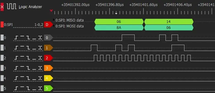
SPI port
A SPI bus screen-printed on the board (with MISO, MOSI, and SCK labels) has been identified. The communication frames have been extracted from this bus. After reviewing the information, it is found that this data exchange does not belong to an SPI FLASH memory, so no useful information is obtained.
SWD port
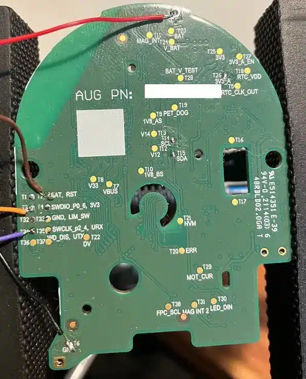
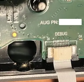
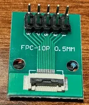
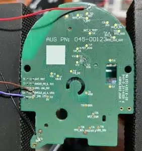
Two SWD debug ports have been located through the labels silkscreened on the PCB, one on the upper side of the board and the other on the lower side. On the bottom side, it has been necessary to solder the connections to the located test points. On the upper side, and whenever possible, it is recommended to do so; the specific connector and an adapter to standard connectors have been soldered.
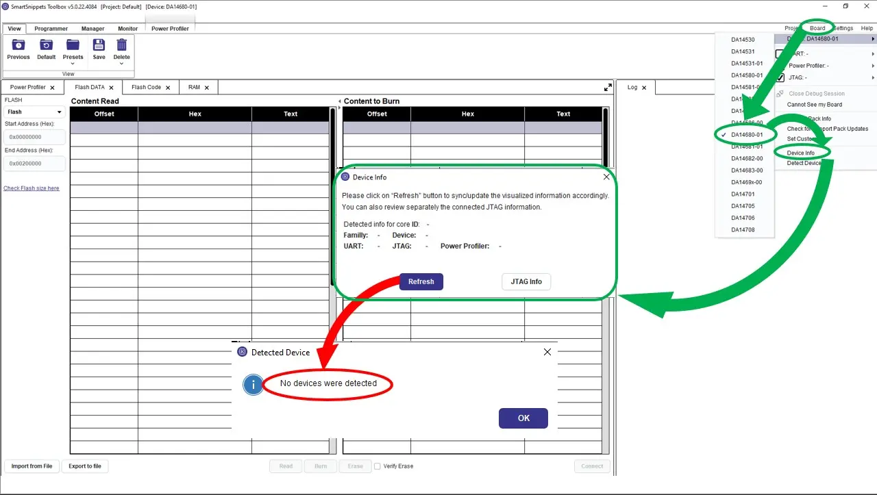
After testing all possible configurations, the microcontroller does not respond to the debug interface, so it is suspected that the tracks are not physically connected to the pins or are disabled by some mechanism that does not allow direct electrical connection.
These conclusions are reached because it has not been possible to read the microcontroller identification after starting the manufacturer’s application (SmartSnippets Toolbox) using a JTAG configured as a SWD debugger.
UARTport
Again, a UART bus has been identified through the silkscreen of the board (TX, RX), in which it has not been possible to capture any communication. As with SWD, this may be due to the device having debug mode disabled.
Risks associated with device components
During an audit, identifying components lets you know if they are outdated and do not receive updates. Sometimes, components are marked as NRND (not recommended for use in new designs) because they are defective or erratic in operation, have defects that cannot be corrected, or use cases where they pose a security problem in themselves. Given these possibilities, the most appropriate thing to do when undertaking a design is to check the life cycle of the products to be used to avoid surprises in the near future.
The components that most frequently suffer security problems are those related to communications, for example, buses such as CANBUS or Bacnet in wired cases and Bluetooth or WiFi in wireless communications.
The DA14680A microcontroller, marked as NRND, stands out in the lock analyzed.
The microcontroller is in charge of BLE communications and locks actuation. It is concluded that the micro is in charge of wireless communications because it is directly connected to the wireless communications receiving antenna, and it is known to be in charge of lock opening and closing because no other devices control the lock.
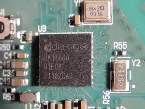 DA14680A has been vulnerable to the Bluetooth Sweyntooth vulnerability, which has been present for over two years and has recently been patched in this microcontroller.
 For this reason, integrated circuits with extended lifetimes should be used. Sometimes, PCB designs are reused, and attention must be paid to the expected life cycle. In this case, if the locks had not been updated through software, they would be vulnerable to reboots with malformed Bluetooth packets, causing a denial of service problem.
Videos have been located where you can see how a device with the same microcontroller and from the same original manufacturer reboots cyclically. Below is the video of how denial of service failures occurs continuously.
Conclusions
It has been possible to identify all the components of the embedded device, and the communications used have been discovered.
The analyzed device does not present vulnerabilities in the design. However, there are aspects for improvement, such as the presence of test points with silkscreens that help to locate communications ports.
No sensitive information has been identified through the I2C and SPI communication buses, and the UART and SWD (JTAG) debug buses are disabled.
As it was not possible to obtain the firmware through the techniques used, it would be necessary to perform the chip-off technique to extract its firmware, which is more complex and has the risk of damaging the integrated (in this case, the DA14680 micro) during the soldering operations.
The analyzed hardware has many components and functionalities, making the task of obtaining information from all of them very time-consuming.
The BGA encapsulation of the microcontroller adds additional security to the lock, preventing it from being read without performing a chip-off.
The overall security level is quite good. While a UART interface and SWD debug port were located, both thanks to the help of the silkscreens, these are protected and disabled. The I2C and SPI communications were captured but did not provide useful information, nor did they allow the firmware or cryptographic keys to be dumped.
The DA14680 integrated unit is noteworthy since it is a vulnerable point that has caused problems in the past, and its support has been announced to be discontinued.
This article is part of a series of articles about unSecuring Smart Locks
- Hardware vulnerabilities in smart locks
- Bluetooth vulnerabilities in smart locks


